- Reduced price
- 10%
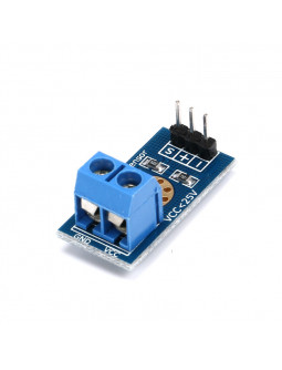
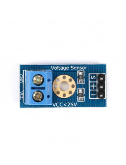
This module is a simple yet highly practical device that utilizes a potential divider to decrease any input voltage by a factor of 5. It enables you to utilize the analog input of a microcontroller to monitor voltages significantly higher than its normal sensing range. For instance, with a 0V - 5V analog input range, you can measure voltages up to 25V. The module is equipped with convenient screw terminals that facilitate easy and secure wire connections.
This module is a simple yet highly practical device that utilizes a potential divider to decrease any input voltage by a factor of 5. It enables you to utilize the analog input of a microcontroller to monitor voltages significantly higher than its normal sensing range. For instance, with a 0V - 5V analog input range, you can measure voltages up to 25V. The module is equipped with convenient screw terminals that facilitate easy and secure wire connections.
The module operates on the principle of resistive voltage divider design, reducing the input voltage by a factor of up to 5. This ensures that the voltage detected by the module's input does not exceed 25V (or 16.5V for 3.3V systems) when using Arduino analog input voltages up to 5V.
Please note that Arduino AVR chips have a 10-bit analog-to-digital (AD) converter, which results in a simulated resolution of 0.00489V (calculated as 5V/1023). As a result, the minimum detectable voltage for this module is 0.02445V (0.00489V x 5).
• Divider Ratio: 5:1
• Resistor Tolerance: 1%
• Max Input Voltage: 25V
• Resister Value: 30K/7.5K Ohm
• Voltage input range : DC0-25 V
• Voltage detection range : DC0.02445 V-25 V
• Voltage analog resolution : 0.00489 V
• 1 x Voltage Sensor Detection Module
This piece of code is designed to read the voltage from an Analog Voltage Divider/Sensor. The sensor has a maximum input voltage of 25V, and the code displays the result on the Serial Monitor of the Arduino IDE. The analog value obtained from the sensor is converted to voltage using the formula: voltage = sensor_value * (5.0 / 1023.0), where 5.0 represents the voltage of the Arduino's power supply and 1023 is the maximum analog value.
To calculate the actual voltage, the code employs the voltage divider formula: Vout = Vin * R2 / (R1 + R2). Here, Vin represents the maximum input voltage, R1 denotes the resistance of one of the resistors in the voltage divider, and R2 represents the resistance of the other resistor in the voltage divider.
To utilize this code, you need to connect the Analog Voltage Divider/Sensor to an analog input pin of your Arduino board (usually A0 for most Arduino boards). Additionally, connect the voltage divider resistors to the input voltage source and ground. It is crucial to ensure that the maximum input voltage does not exceed 25V. Lastly, you will need to customize the code by replacing the values of R1 and R2 with the specific resistances used in your voltage divider circuit.
const int sensor_pin = A0; // Pin connected to the output of the voltage divider
void setup() {
Serial.begin(9600);
}
void loop() {
// Read the analog value from the sensor
int sensor_value = analogRead(sensor_pin);
// Convert the analog value to voltage (5V = 1023)
float voltage = sensor_value * (5.0 / 1023.0);
// Convert the voltage to the actual voltage using the voltage divider ratio
float actual_voltage = voltage * (R1 + R2) / R2;
// Print the actual voltage
Serial.print("Actual voltage: ");
Serial.print(actual_voltage);
Serial.println(" V");
// Wait for 1 second before taking the next reading
delay(1000);
}

This module is a simple yet highly practical device that utilizes a potential divider to decrease any input voltage by a factor of 5. It enables you to utilize the analog input of a microcontroller to monitor voltages significantly higher than its normal sensing range. For instance, with a 0V - 5V analog input range, you can measure voltages up to 25V. The module is equipped with convenient screw terminals that facilitate easy and secure wire connections.