- Reduced price
- 20%
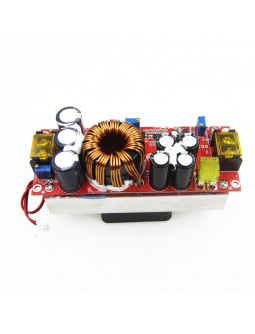
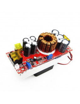
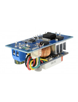
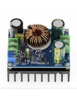
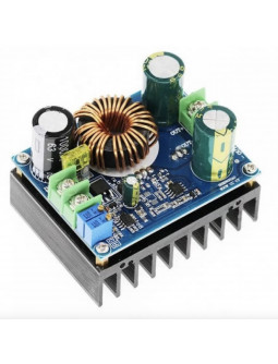
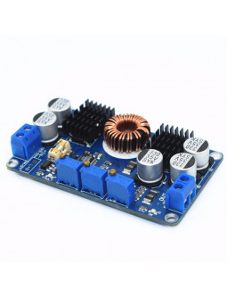
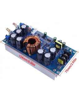
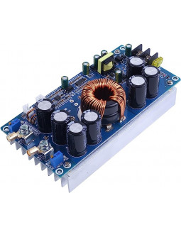
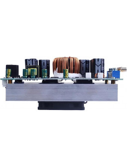
The 1800W Step Up Converter is a powerful and versatile module designed for various applications such as boosting lead-acid batteries, lithium batteries, solar cells, and electric vehicle power systems.
The 1800W Step Up Converter is a powerful and versatile module designed for various applications such as boosting lead-acid batteries, lithium batteries, solar cells, and electric vehicle power systems. It allows for adjustable output voltage and current, making it suitable for different devices and charging scenarios. With advanced features like temperature-controlled fans, high-grade insulation materials, and efficient power conversion, this module provides reliable and efficient performance. It also offers comprehensive protections, indicator lights, and high-frequency capacitors for enhanced safety and stability.
• Wide Voltage Range: The module supports voltage options from 10V to 60V, allowing flexibility for various indoor electronics and power systems.
• Adjustable Output Voltage and Current: It can boost and provide a variable output voltage or current, catering to different device requirements. It delivers a powerful output of 1800W and 40A.
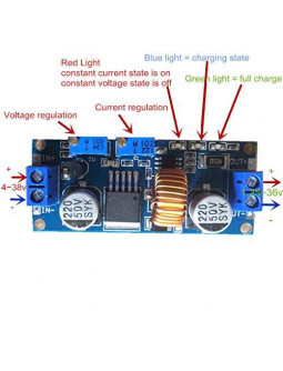
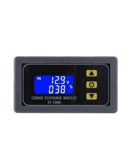
• LED Display and Indicator Lights: The LED display allows convenient monitoring of output voltage and current. Indicator lights for undervoltage, overcurrent, and power provide visual status information.
• Multiple Protections: The module features protections against undervoltage, over temperature, short circuits, and reverse connection, ensuring safe operation for both the module and connected devices.
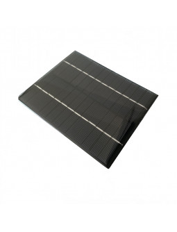
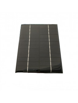
• Versatile Application: It is suitable for a range of applications, including boosting electric vehicle batteries, charging electric bikes, and integrating with solar cells or other power sources.
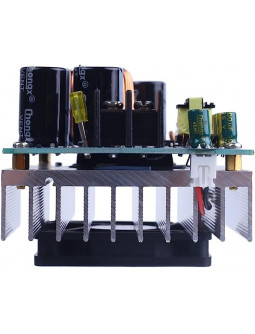
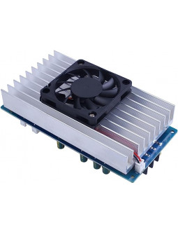
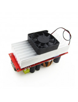
• Efficient Cooling: The airfoil-type heat dissipation design and temperature-controlled fans ensure effective heat dissipation and a balance between cooling performance and noise level.
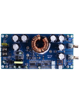
• High-Quality Components: The module utilizes high-grade alumina insulation materials, large power margin power tubes, and large-size magnetic rings for enhanced performance and reliability.
• High Conversion Efficiency: With a conversion efficiency of up to 98.1%, the module provides efficient power conversion for optimized energy utilization.
• Compact and Durable: The module is compact in size and features a robust construction, with high-frequency capacitors for low output ripple, low heat generation, and extended lifespan.
• Output Power: 1800W
• Input Voltage Range: 10V-60V
• Output Voltage Range: 12V-90V
• Input Current: 40A
• Output Current: 22A
• Dynamic Response Speed: 5% load current change (300us)
• Conversion Efficiency: 48V to 60V 8A (98.1%), 48V to 72V 8A (98.1%), 48V to 84V 8A (97.6%)
• Load Regulation: 10% to 50% load (72V output)
• Ripple & Noise: 20MHz Bandwidth (48V-72V 4A) 100mVp-p
• Switching Frequency: VIN=48V, VO=72V, 4A (110kHz)
• No-load Current: VIN=48V, VO=72V (18mA)
• Output Short Circuit Protection: Yes
• Input Reverse Protection: Yes
• Storage Humidity: 95%
• Working Temperature: -20 to 65°C
• Storage Temperature: -40 to 125°C
• Temperature Rise During Work: 48V to 60V 5A (45°C)
• Over Temperature Protection: 60°C
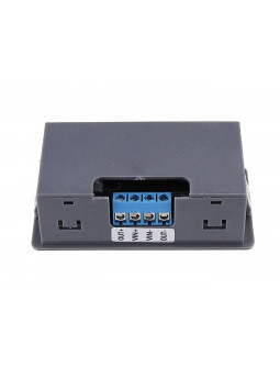
• Wiring Method: IN input, OUT output (No welding, terminal blocks)
• Cooling Method: Strong wind cooling
• Appearance Size: 130 (L) * 51 (W) * 80 (H) mm (with copper pillars)
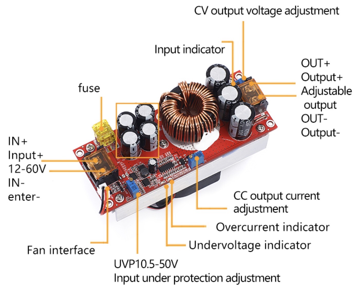
To adjust the output voltage, use a flat-blade screwdriver on the "V-ADJ" terminal while the power is turned on and there is no load. Rotate the potentiometer clockwise to increase the voltage and counter clockwise to decrease it. Keep in mind that due to the large capacitance of the output capacitor, adjusting the output voltage from a higher value to a lower value will result in a slower response. The adjustment range of the instrument is limited.
To set the output current, turn the "CC A-ADJ" potentiometer counter clockwise approximately 30 turns. Connect the LED battery or other loads, and then slowly rotate the "CC A-ADJ" potentiometer clockwise until you reach the desired current. For battery charging, after the battery has been discharged, connect it to the output and adjust the "CC A-ADJ" to the desired current. It is important to use a discharged battery for accurate adjustment, as the charging current decreases as the battery retains more power. Never attempt to adjust the current by short-circuiting the output, as the boost module's circuit structure does not support this method.
The purpose of low battery protection is to prevent battery over-discharge when the input power is supplied by a battery. This protection is also necessary when using a switching power supply. There are two methods for adjusting low battery protection:
For example, to set the low battery protection at 12V, connect an 11V voltage to the input of the power supply module. Use a flat-blade screwdriver to adjust the RV1 potentiometer (clockwise increases the protection voltage, counter clockwise decreases it) until the UVLO light illuminates. This indicates that the low battery protection voltage is set at 11V. The power module will not start when the battery voltage drops to 11V (input voltage equals output voltage). The power supply will resume operation only when the input voltage exceeds 11V.
Connect the input to either a battery or a switching power supply. If the UVLO light on the board is off, turn the RV1 potentiometer clockwise to turn on the UVLO light. Then, turn it clockwise two more times. If the UVLO light is on, turn the RV1 potentiometer counter clockwise to turn off the UVLO light, and then turn it counter clockwise two more times. This method is suitable for voltage ranges from 10V to 45V.
• Ensure that the output positive and negative terminals are not reversed or short-circuited.
• When using the module as a booster drive power supply for electric vehicles, the input voltage must be above 24V, and the power of the electric vehicle should be less than 500W. Inductive loads, such as electric vehicle motors, experience high current during start-up and uphill travel, so it is crucial to leave sufficient power margin.
• When using batteries, switching power supplies, solar panels, generators, or other input sources, make sure to set the appropriate battery protection voltage to avoid damaging the battery and power supply.
• Adequate ventilation and heat dissipation should be maintained during prolonged operation at high current, high power, or full load to prolong the service life of the power supply.
• Note that the module can only step up the voltage and cannot step it down. It cannot provide power to electrical equipment that requires a lower voltage than the input voltage. For example, it cannot charge a 12V battery with a 24V battery or supply power to devices with lower voltage requirements. Avoid operating at full load for extended periods and maintain a margin of 20% during continuous operation. Additionally, pay attention to ventilation and heat dissipation.
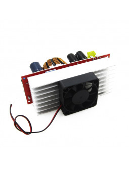
• 1 x 1800W 40A 10V-60V to 12V-90V Step-Up Converter With Heat Sink and Fan (CC/CV)

The 1800W Step Up Converter is a powerful and versatile module designed for various applications such as boosting lead-acid batteries, lithium batteries, solar cells, and electric vehicle power systems.